FAConstructor
===
The fiber arcitecture constructor (FAConstructor) allows a simple and effective creation of fiber models based on mathematical functions or the manual input of data points. Models are visualized during creation and can be interacted with by translating them in the 3-dimensional space.
The source code can be downloaded [here](https://github.com/3d-pli/FAConstructor).
A Singularity container and Windows installer might become available at a later date.
**Note:**
Currently, only Linux distributions and macOS are fully supported. macOS might not be supported in future versions due to the deprecation of OpenGL starting at macOS 10.14 (Mojave).
While the program is Windows compatible no installer is currently available. Until then please compile the program using CMake, Visual Studio and vspkg.
Installation
===
## Compile the program
### System Requirements
**Minimal Requirements:**
* Graphics card supporting OpenGL 3.3 natively
* 1GiB RAM
* 2 core processor built since 2007
* 100 MB disk space
**Recommended Requirements:**
* At least NVIDIA Geforce GTX 750Ti / AMD RX560 or more powerful GPU
* 16 GiB RAM for large models
* 4-core processor
### Required programs and packages
* CMake 3.5
* Qt5 5.5
* C++/C compiler supporting C++14
* Make
* HDF5
### Optional programs and packages
* Boost Math (Version 1.65 or newer required)
* OpenMP
* GPerfTools
### Install instructions
Install all needed dependencies using your package manager or by compiling them from source.
Example using Ubuntu or Debian:
```sh
sudo apt install gcc g++ cmake make qt5-default libhdf5-dev libboost-math-dev
```
Example using Manjaro/Arch:
```sh
sudo pacman -S gcc cmake make qt5-base hdf5 boost
```
#### Clone repository
Clone the repository to your local folder via SSH or HTTPS
SSH:
```sh
git clone git@github.com:3d-pli/FAConstructor.git
cd FAConstructor
```
HTTPS:
```sh
git clone git@github.com:3d-pli/FAConstructor.git
cd FAConstructor
```
#### Compile the program
When using Debian the following command may be required before compiling:
```sh
export CPATH=/usr/include/hdf5/serial/:$CPATH
```
Execute the following commands in the project folder:
```sh
mkdir build
cd build/
cmake ..
make -j
```
If everything ran successful the program is located at `FAConstructor/build/FAConstructor` and can be started from there.
#### Install program
After a successful compilation running `make install` will install the program and the corresponding headers and libraries at `/usr/local`
#### Changing options
By default the following options are set:
```
BUILD_TESTING = ON
CMAKE_BUILD_TYPE = Release
USE_OpenMP = ON
CMAKE_INSTALL_PREFIX = /usr/local
```
You are able to change this options with `ccmake` or by defining them when calling `cmake`.
Additionally, when using `CMAKE_BUILD_TYPE = Debug` the option `USE_GPerfTools` is available but is disabled by default
## Run the program
### Program options
Starting the program is possible by using the desktop entry created after the installation of the program or by typing `FAConstructor` in a terminal.
Optionally a file can be opened directly by passing the file as the first argument in the CLI or by opening a .dat or .h5 file directly from a file explorer.
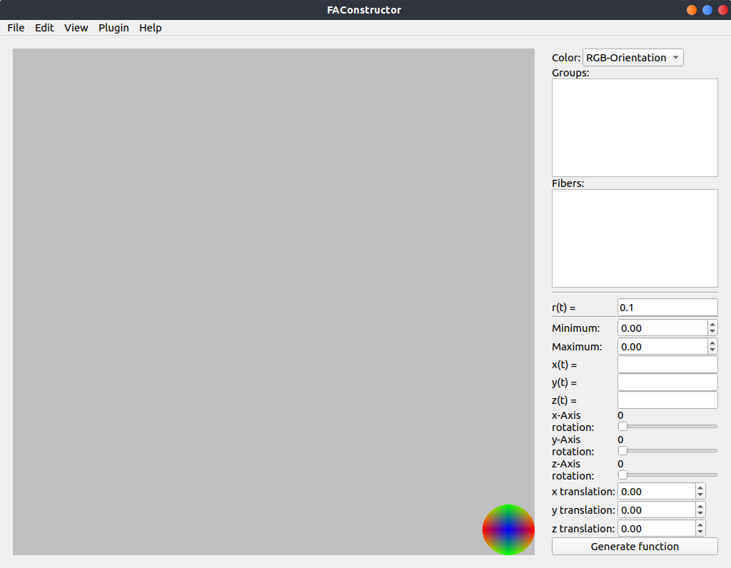
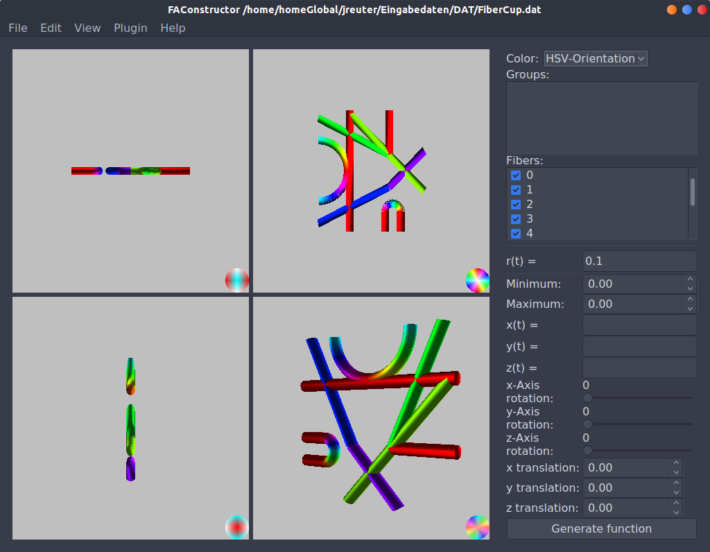
The default view when firs opening the program can be seen below
Plugins
===
## Develop Plugins
The FAConstructor tool can be extended using plugins. When installing the program a library will be installed at your configured path which can be used to implement own plugins which can then be accessed at runtime.
### Prerequisites
To implement libraries the program should be installed already on your computer. You are also able to just use the header files and link them with the `libFAC.so` generated by the build files.
A minimal project usable for plugin implementation can be found [here](https://gitlab.version.fz-juelich.de/INM1-FA/Private/reuter1/faconstructor-plugins/generalplugin).
The plugin will be executed using the `run()` method. Additional information can be gathered by the header files especially `plugindata.h`.
All fiber objects can be found in the `FAC::FiberPool` class. An instance can be accquired by executing `&FAC::FiberPool::getInstance()`. This class allows the direct manipulation of generated fiber objects.
### Required packages / Headers
* Qt5 in the same version as the compiled FAConstructor
* Compiled FAConstructor
### Installing the Plugin
Depending on your path set in the [Settings](#Settings0) your compiled shared library can be put in one of your plugin folders. When starting the program afterwards FAConstructor will try to load the plugin. If an error occurs it will be written to the console output.
### Running the Plugin
All plugins found can be executed by clicking on the **Plugin** menu in the menu bar. There all valid plugins are listed. Clicking on one will execute the `run()` method in your compiled shared library.
Usage
===
## Create models
### Creation
Two ways are implemented allowing the user to easily define fiber tracts which will be visualized by the program.
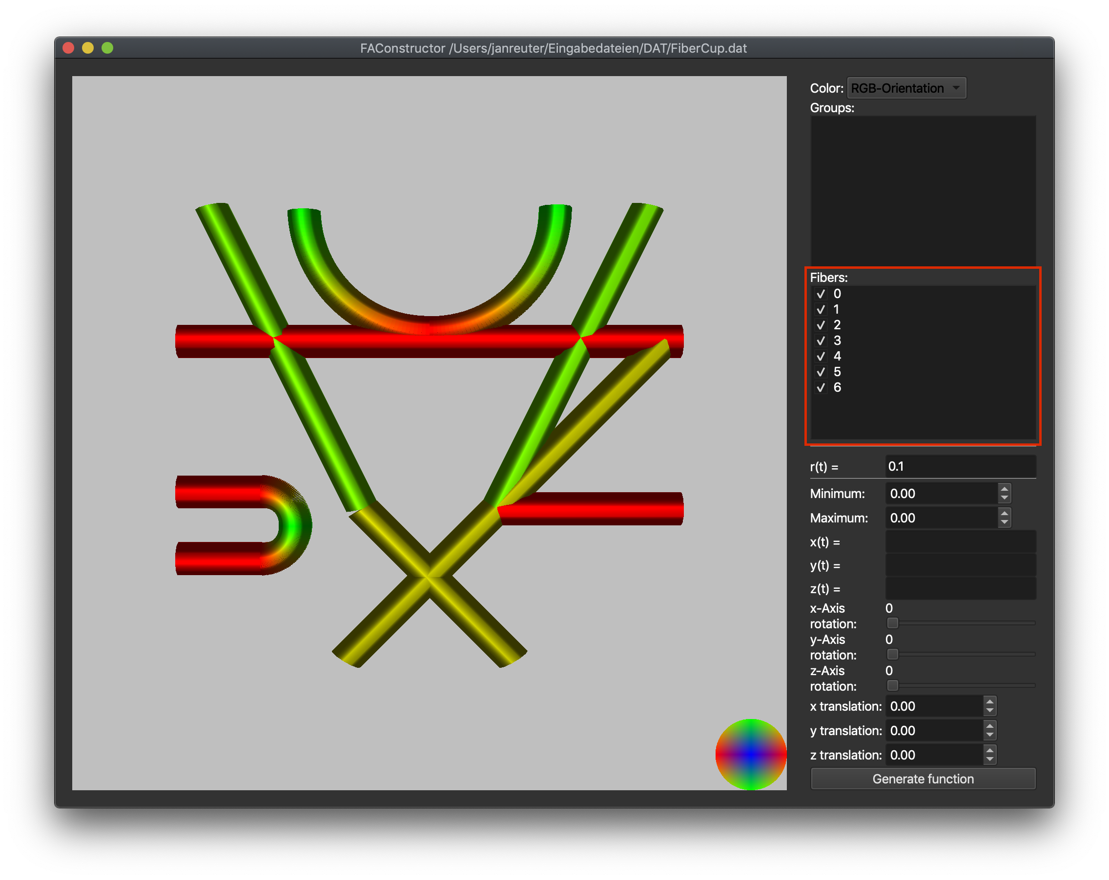
#### Creation by defining functions
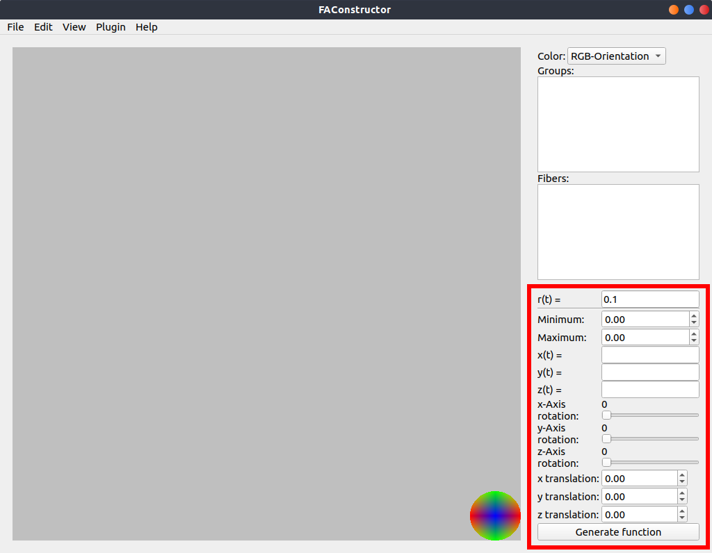
When creating fiber tracts by parametric functions the area shown in the red square needs to be used.
The following options are available:
| Parameter | Function |
| --------------- | ---------------------------------------------------------------------- |
| r(t) | Parametric function describing the radius of the generated fiber tract |
| Minimum | Minimal evaluation value |
| Maximum | Maximal evaluation value |
| x(t) | Parametric function describing the position in the x-axis |
| y(t) | Parametric function describing the position in the y-axis |
| z(t) | Parametric function describing the position in the z-axis |
| x-Axis rotation | Rotation around zero position in x-axis |
| y-Axis rotation | Rotation around zero position in y-axis |
| z-Axis rotation | Rotation around zero position in z-axis |
| x translation | Translation in x-axis after rotation |
| y translation | Translation in y-axis after rotation |
| z translation | Translation in z-axis after rotation |
The final points are evaluated using the following function:
$$
p_i = \vec{x}_{translation} + \vec{y}_{translation} + \vec{z}_{translation} + {M_x} \cdot {M_y} \cdot {M_z} \cdot \begin{pmatrix}
x(t_i) \\
y(t_i) \\
z(t_i) \\
r(t_i)
\end{pmatrix} \\
t_i = \frac{i}{N} \cdot (t_{max} - t_{min}) + t_{min} \\
i \in [0..N], N \in N_+
$$
Upon pressing the **Generate function** button the fiber object will be generated and rendered in the central area.
#### Creation by manual input
Fiber objects can be created using the corresponding submenu at:
**Edit** → **Fiber** → **Import from Input**
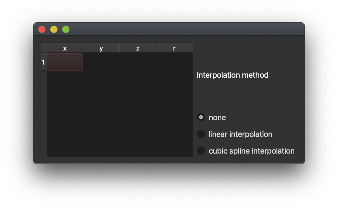
Here individual fiber points can be described by writing the corresponding position and radius in each row. At least two points have to be defined to create a fiber object. Missing entrys are deleted when closing the window while the fiber object is generated.
Additionally interpolation methods can be applied. **Linear interpolation** does increase the density of fiber points and can be useful for later application of the generated fiber model while **Cubic Spline interpolation** smoothens out the path. The amount of fiber points generated by those methods can be changed in the [Settings](#Settings0).
***Note:** At least 6 points are needed when using Cubic Spline interpolation. The interpolation results might differ when compiling with or without the Boost library.*
For shortcuts in this window see [Shortcuts](#Shortcuts0)
### Editing
Created fiber objects can be altered after their creation. Every fiber object is assigned a unique index shown in the marked area in the following figure.
***Note:** Here, only options which alter the fiber objects are discussed. For interaction purposes, see [Interaction](#Interaction0)*
Every of the following options can be applied to one or more fiber objects at the same time. To apply an option simply select the desired fiber objects and choose the option at:
**Edit** → **Fiber** → **[Option name]**
Additionally fiber objects can be edited by double clicking the entry in the list.
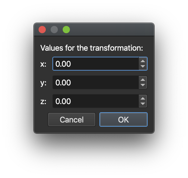
#### Translate fiber objects
Selected fiber objects can be translated using the **Translate selected** option.
A window will open asking for the desired translation in every axis. Clicking **OK** will apply the translation while **Cancel** or closing the window will not change the selected objects.
When translating, every fiber point is changed with the following formula:
$$
p_i = \vec{x}_{translation} + \vec{y}_{translation} + \vec{z}_{translation} + p_i \\
i \in [0..N], N \in N_+
$$
#### Duplicate fiber objects
Selected fiber objects can be duplicated using the **Duplicate selected** option.
New fiber objects are created with exactly the same coordinates and are placed below all existing fiber objects. Existing fiber objects are not altered.
#### Delete fiber objects
Selected fiber objects can be deleted using the **Delete selected** option.
These objects are removed from any existing group. The index of fibers with a higher index than the deleted fiber objects are altered as their index is corrected to present a list from $0$ to $N$ where $N$ presents the amount of fiber objects.
#### Nest fiber objects
Created fiber objects can be filled using the **Create bundle** option. When using the option a window is opened asking for two parameters.
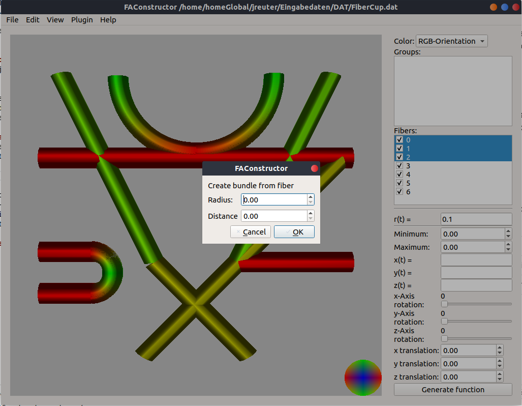
| Parameter | Function |
| --------- | ------------------------------------------------------- |
| Radius | Radius of each individual fiber after the creation |
| Distance | Distance between the center of each nested fiber object |
The selected fiber objects are filled using an equidistant triangular grid. The amount of fibers is determined by the minimum radius over the trajectory of the fiber object. When the radius increases compared to the minimal radius, the distance between the nested fiber objects increases accordingly.
Clicking **OK** will create bundles of all selected fibers while **Cancel** or closing the window will not change anything.
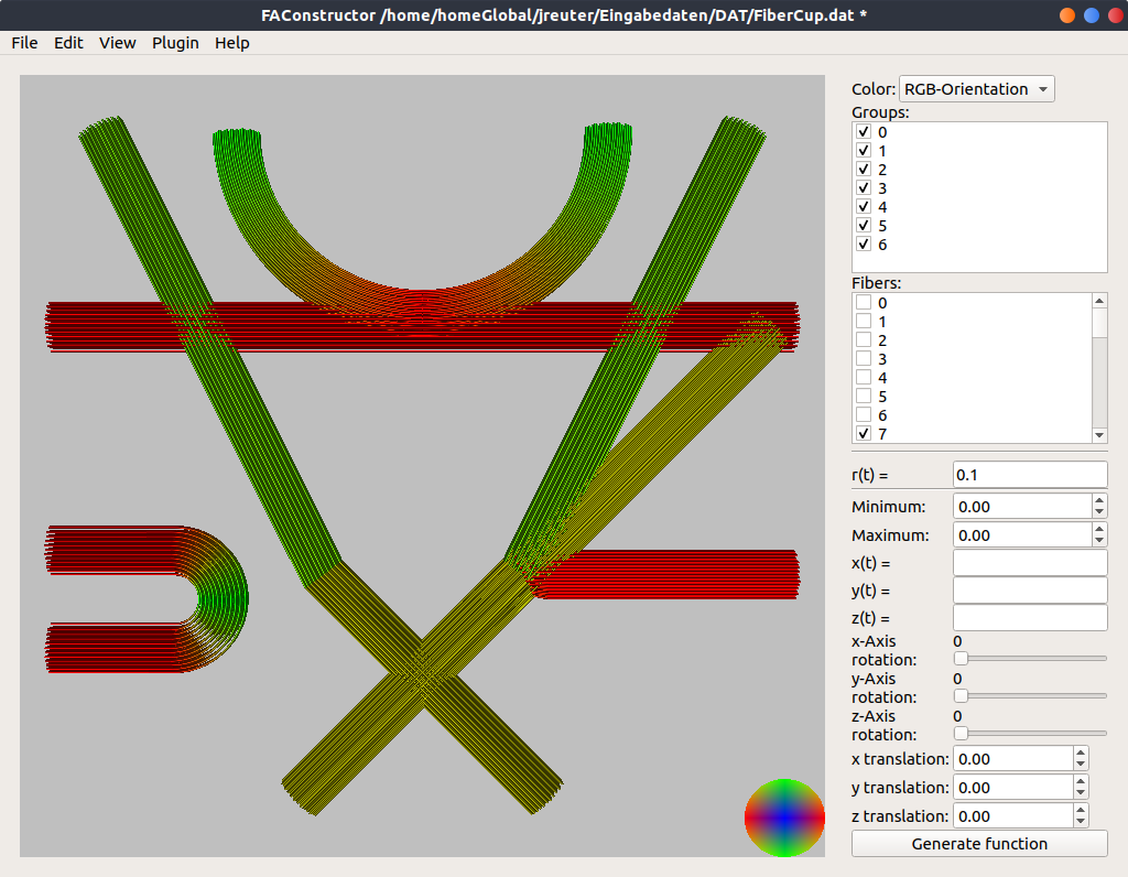
All nested fiber objects of a fiber object are stored in a group allowing further manupulation. The original fiber object is kept.
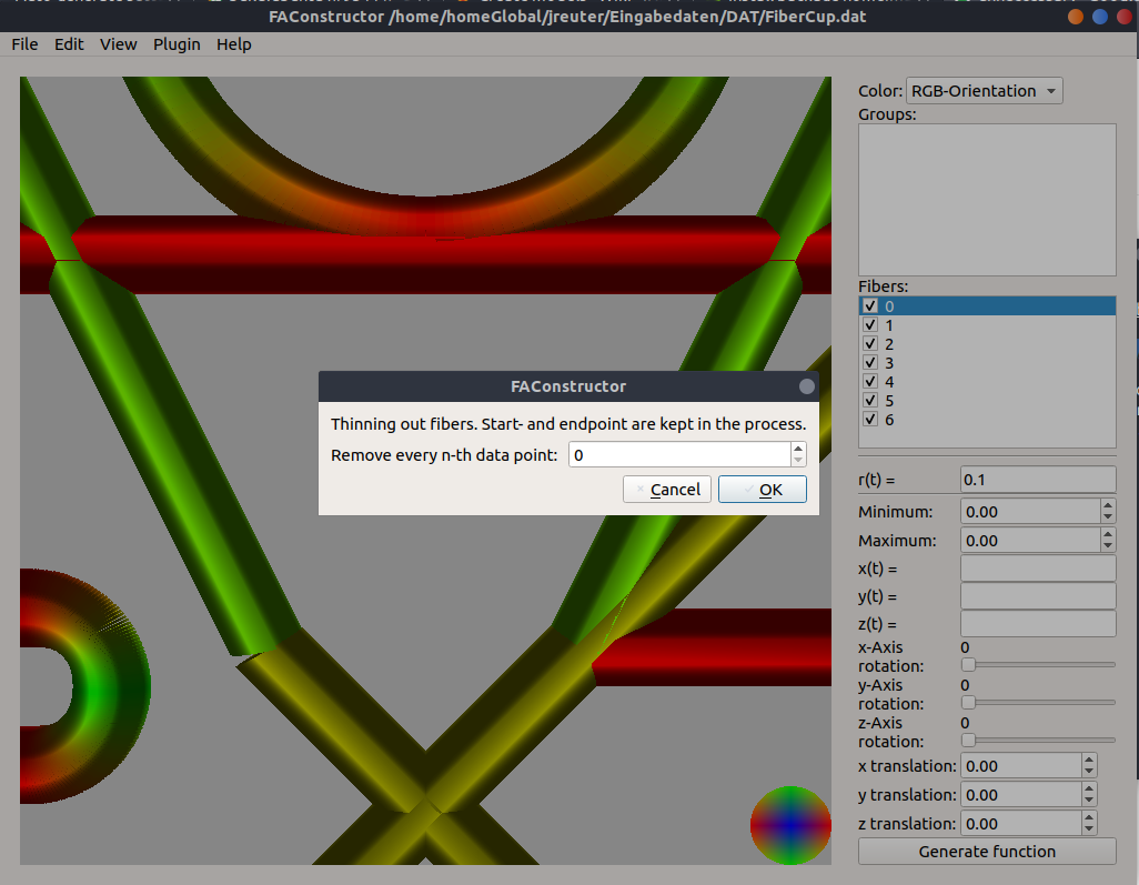
#### Thin fiber objects
After creation fiber objects might contain too many data points describing the object. This results in a possible decrease in the frame rate as well as unnecessary big files when saving the data. Therefore fiber objects can be thinned.
Using the **Thin selected** option the user is asked to type in a parameter. The number corresponds to every $n$-th data point which will be removed in the process.
### Grouping
Groups are a way to describe multiple fiber objects which correspond with each other. They are automatically created when filling fiber objects but are also createable by the user.
Using the **Edit** → **Group** → **Create group** option selected fiber objects will be combined to a group. Each fiber object will remain in the Fibers list.
Groups offer most operations fiber objects have like translating or rotating them.
### Saving and reading
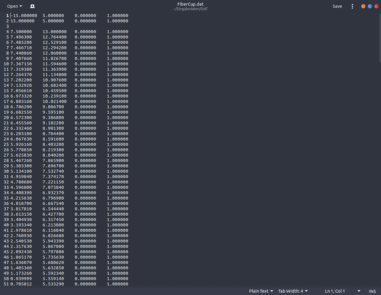
#### .dat file
The program is able to read and write .dat files containing fiber point coordinates and their corresponding radius. Each fiber is seperated by an empty line. Coordinates are seperated using `[TAB]` as the seperator. Groups are not saved or read when using this file format.
An example file is shown below:
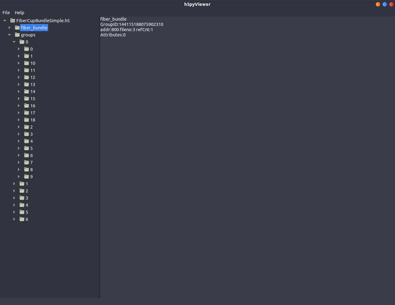
#### HDF5 file
Additionally HDF5 files can be created with the following structure:
`/fiber_bundle/[NUMBER]/points`
`/fiber_bundle/[NUMBER]/radii`
`/groups/[NUMBER]/[Symbolic link to fiber object NUMBER]`
The number corresponds to the number seen in FAConstructor. `points` contains a data set with $n$ rows and 3 entries each. Constructed files with FAConstructor contain a `radii` dataset with $n$ rows and one entry. When reading other files, only the first entry is considered and rendered.
An example file is shown below:
## Interaction
FAConstructor grants several ways to interact with the generated fiber models such as moving, rotating or hiding them.
### Hiding / Showing fiber objects
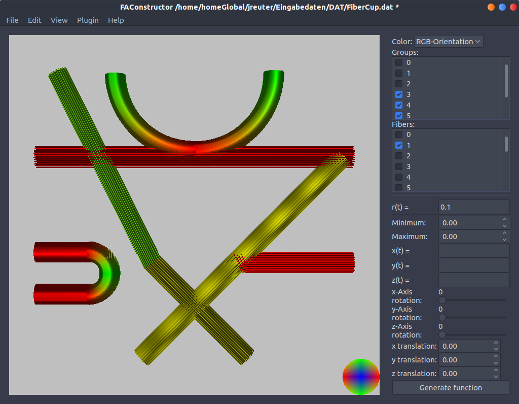
Fiber objects and groups can be hidden by clicking on the checkbox next to the corresponding number. When hiding a group, all underlying fibers are hid automatically. If all fibers of a group are hidden the checkbox next to it is deactivated.
Hiding objects may be effective when facing large models and may increase the frame rate. Hidden elements are still saved when exporting the model.
### Rotating / Translating the view
***Note:** Keyboard shortcuts will not be discussed here. See [Shortcuts](#Shortcuts)
for available options*
Generated models are interactively viewable in the three dimensional space. Using the **left mouse button** users can move the camera upwards or sideways while the **right mouse button** rotates the view in the x-axis and y-axis. Using the **middle mouse button** the z-axis can be rotated.
The mouse wheel is used to zoom in or out of the model.
The current view can be reset using the **View** → **Restore view** option. The current model is then centered and every movement option is based around the newly centered point.
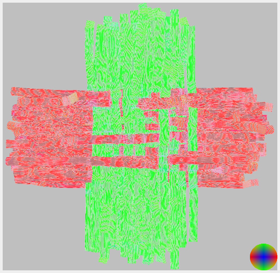
Using the **Color** option in the top right corner of the program the visualized model can be colored in different ways:
* Orientation based coloring in the RGB color space
* Orientation based coloring in the HSV color space
* Coloring based on the fiber indice
* Plain gray for all objects
### Showing different angles
## Settings
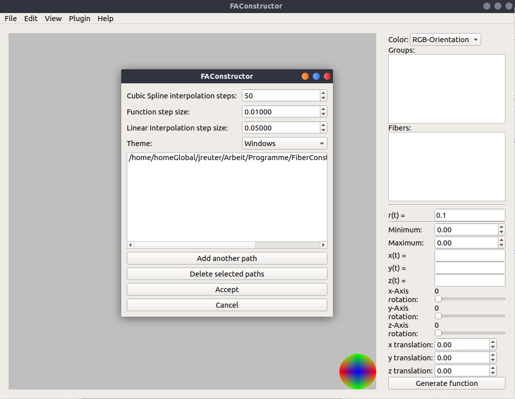
Some parameters are able to be changed. This includes the generation of fiber objects through functions and input as well as the theme and plugin search path.
Please keep in mind that some options do require a restart of the program before the new settings take effect.
### Parameter sizes
| Parameter | Function |
| -------------------------------- | -------------------------------------------------------------------------------------------------------------------------------------------------- |
| Cubic Spline interpolation steps | The amount of points generated when using the cubic spline interpolation during the creation process with manual input |
| Function step size | $\Delta t$ between $t_{min}$ and $t_{max}$ when creating fiber objects through parametric functions. |
| Linear interpolation step size | The the step size declaring the amount of points generated when using the cubic spline interpolation during the creation process with manual input |
### Plug-In paths
Plug-Ins can be loaded when the program starts. Here search paths can be defined.
### Themes
Drop down menu showing all available themes for the user.
**Note:** The GTK2+ theme might cause crashes on start up on certain operation systems. To prevent this, the Qt5 Configuration Tool needs to be set to `gtk2`
Shortcuts
===
## Interface
| Shortcut | Function |
| ---------------- | ---------------- |
| CTRL + N | New File |
| CTRL + O | Open File |
| CTRL + S | Save File |
| CTRL + Shift + S | Save File as ... |
| CTRL + Shift + E | Export File |
| CTRL + W | Close File |
| CTRL + Q | Quit |
## Interaction
| Shortcut | Function |
| -------- | ------------------------------------- |
| F6 | Show only orthogonal view from x axis |
| F7 | Show only orthogonal view from y axis |
| F8 | Show only orthogonal view from z axis |
| F9 | Show only 3D view |
| F10 | Show all views |
| R | Restore single view to default |
| CTRL + R | Restore all views to default |
## 2D view
| Shortcut | Function |
| -------- | ---------------------- |
| W | Upwards movement |
| A | Left movement |
| S | Right movement |
| D | Downwards movement |
| Q | Move in-plane forward |
| E | Move in-plane backward |
## 3D view
| Shortcut | Function |
| -------- | ---------------------- |
| W | Upwards movement |
| A | Left movement |
| S | Right movement |
| D | Downwards movement |
## Creation by manual input
| Shortcut | Funktion |
| ------------- | ------------------------- |
| CTRL + Delete | Delete selected row |
| CTRL + J | Insert row above selected |
| CTRL + K | Insert row below selected |